
System Science - Part 4: Digital Considerations
Getting To Grips With Digital I/O, Expansion & Clocking.
Audio interfaces don’t only have analogue connections. They also have digital inputs and outputs. With a few exceptions, digital inputs can’t be used to directly record musical instruments or microphones; their primary purpose is expansion. The role of digital I/O is to allow additional recording hardware to be attached, increasing the capabilities of the audio interface.
In other words, what digital inputs and outputs really do is make it possible to add extra analogue inputs and outputs. But why do this by a roundabout route? Why not just build more analogue I/O into the interface in the first place?
Every analogue input and output requires its own electrical circuitry and analogue-to-digital or digital-to-analogue converter, and takes up space on the front or back panel; so each one we add increases the cost of the interface and makes it harder to fit everything in. By contrast, digital expansion formats are incredibly compact. Depending on its format, a single digital input can accommodate two, eight, 56 or even 64 channels of audio — even more if we enter the world of audio over IP.
Digital expansion also leaves the user free to choose the additional input and output types that he or she needs. One person might find herself wanting an extra eight microphone inputs; another might need sixteen line-level inputs to connect a mixing console; someone else may wish to add more outputs in order to integrate studio hardware at mixdown. All of these possibilities can be catered for by a couple of tiny digital connectors.
Clock Wise
Digital audio consists of a series of ‘samples’, measurements of the level of a signal that are taken at regular intervals. In the case of standard CD-quality audio, there are 44,100 samples per second. To maintain this regularity, every digital audio device needs a timing reference or ‘clock’.
If we’re just using a single audio interface on its own, it will happily run from its own internal clock. Likewise, there are no clocking issues involved in connecting other hardware in the analogue domain. However, consider what happens when we digitally connect a second device, such as a mic preamp with a digital output, to our audio interface. In this case, the interface receives a stream of samples that are spaced not according to its own clock signal, but to that of the mic preamp. For a while, we might be lucky and find that the two clock signals run in sync, but as no two clocks are absolutely identical, one of them eventually will fall slightly behind the other, and the interface will no longer be able to make sense of the data it’s receiving.
Keeping the parts of your digital audio network in sync is very important.
The only way for digital audio to be transmitted successfully from one device to another is for the two devices to share the same clock signal. Or, to put it another way, in any studio where devices are connected digitally, one of them needs to be the clock ‘master’, and all the others must be clock ‘slaves’, accepting their timing reference from the master clock. The ways in which this is done vary depending on how many devices we’re connecting, and in what way.
Socket To Me
For reasons that are partly functional and partly historical, you can find several different types of digital input and output on typical audio interfaces. And just as in the world of USB cables, there is a confusing relationship between the type of signal that’s being carried, and the type of connector used to link the sending and receiving device.
One of the best-established standards in the studio world is AES3, sometimes known as AES/EBU. Each AES3 connection can carry a stereo, 24-bit digital audio signal at sample rates of up to 96kHz. The way in which this stream of data is formatted is always the same, and this formatting is the main feature that defines the standard; but the physical arrangements used to transmit it can vary. Older high-end studio gear, including audio interfaces, typically has AES3 inputs and outputs on three-pin XLR sockets. These are identical to the sockets used for connecting microphones to analogue inputs, and indeed, it’s possible to use standard microphone cables to send AES3 signals over short distances.
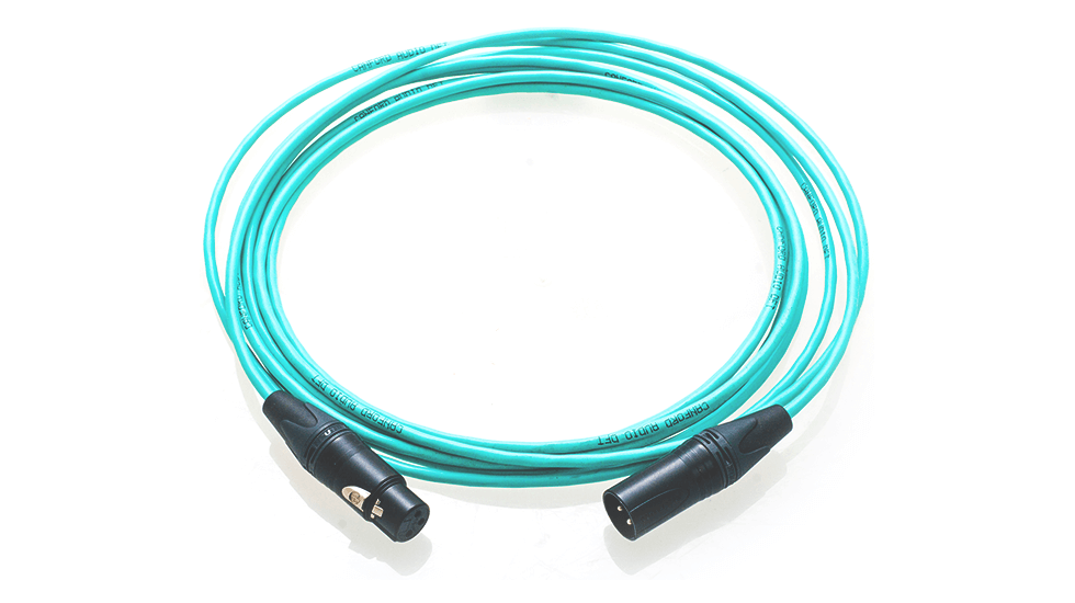 As well as being the standard way of connecting microphones and other analogue gear, XLR sockets are also widely used for stereo digital audio in the AES3 format. (Photo: Canford Audio)
However, signals encoded in the AES3 data format can be sent over other forms of connection, too. Where long cable runs are needed for large broadcast installations and so on, a circular connector called a BNC socket is often used. At the other end of the scale, in home and project-studio gear, the humble RCA phono socket is commonly found. AES3 data sent over phono sockets is often called ‘S/PDIF’, reflecting its origins as the Sony and Philips Digital Interface Format.
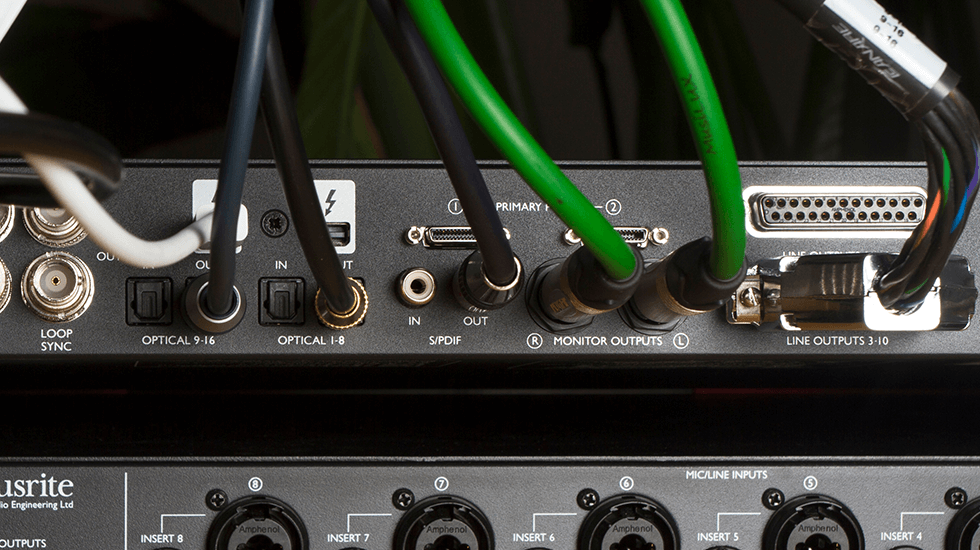
The TOSlink optical connector can carry digital audio in either the stereo S/PDIF format or the eight-channel ADAT format. It is implemented here on the Focusrite Red 8Pre in the latter configuration, labelled ‘Optical 1–8’. The so-called S/PDIF (Sony/Philips Digital Interface Format) digital format is virtually the same as AES3, but uses unbalanced RCA phono connectors.
All three variants mentioned above represent the AES3 data electrically, but there is also a variant that represents it optically. Sometimes known as TOSlink, this carries exactly the same data in the same format, but as pulses of red light rather than alternating high and low electrical voltages.
AES3 sockets on XLR or BNC are usually found only on high-end professional equipment, but the majority of audio interfaces aimed at home and project-studio owners feature a single stereo S/PDIF input and output on phonos and/or optical sockets.
Though the physical connection may vary, the sequence in which the samples are sent is always the same, and AES3 data always includes an ‘embedded’ clock signal. What this means in practice is that if you have a stereo mic preamp with an AES3 digital output, and you connect this to the corresponding input on your audio interface, the interface will receive not only the data but the timing reference needed to make sense of it. However, since the entire interface needs to operate from a single clock reference, you’ll need to switch it to use this clock source. This is usually done in the interface’s control panel software. Both devices must be operating at the same sample rate.
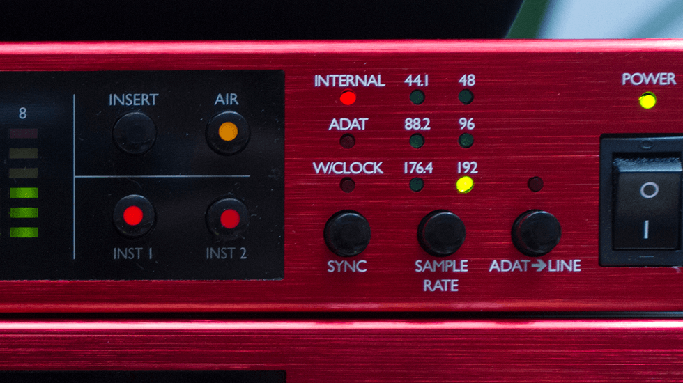
When you’re connecting other equipment to your audio interface digitally, it’s vital to select the appropriate clock source from the front panel. This close-up shows a Focusrite Clarett OctoPre (top) set up as the master clock for a Clarett 8PreX.
ADAT
AES3 and S/PDIF are ubiquitous and useful, but in most cases they offer only limited potential for expansion. Each input and output can only carry a stereo signal, and once we start adding more of them, we risk creating complicated clocking problems. Where greater numbers of additional channels are required, therefore, we often find another standard called ADAT or Lightpipe, originally developed by Alesis for their innovative eight-track digital recorders in the 1990s. ADAT carries digital information in a completely different format from AES3 — but, confusingly, it uses the same optical connectors and cables! In fact, many audio interfaces offer just a single optical input and output, which can be switched to accept either format.
Like AES3, an ADAT signal contains its own embedded clock. Unlike AES3, however, it can contain up to eight channels of 24-bit audio at standard sample rates. Sending eight channels of 88.2 or 96kHz audio over ADAT requires two sets of ports and support for an extension to the ADAT protocol called S/MUX. A single ADAT optical input is therefore a very convenient and cost-effective way to add eight analogue inputs to a recording system — a number which is often sufficient to transform its capabilities. Most audio interfaces that cater to the home and project-studio markets thus offer one or two optical inputs and outputs.
Word Clock
In theory, then, an audio interface with two sets of ADAT optical I/O allows us to add up to sixteen analogue inputs and outputs by connecting other devices that use the same format. But let’s suppose we want to increase the number of analogue inputs to our system by adding two eight-channel mic preamps. A mic preamp has no need to receive audio coming from the computer, so there’s no reason for it to have an ADAT input: to do its job it need only have an output. However, if a device doesn’t have an ADAT input, it can’t use the ADAT signal from another device as its clock reference. In other words, a preamp that only has a digital output can’t be a clock slave: it can only be a clock master, and each system can only contain one clock master.
Similar considerations apply when we want to use ADAT and AES3 connections at the same time, and they become even more of a problem when we have multiple pieces of digital gear linked together. We quickly reach a point where it’s not possible to rely on the embedded clock reference in ADAT or AES3 signals, because there’s no way to slave everything to a single master.
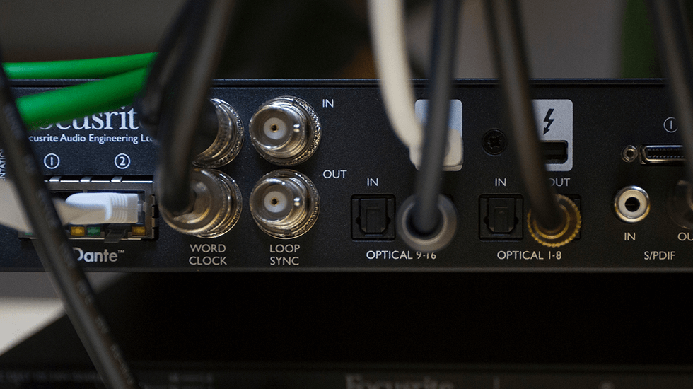
Where a single master clock signal needs to be widely distributed, it’s often necessary to send it separately from audio signals using dedicated ‘word clock’ cables and connectors. Loop Sync, shown here on the back of a Red 8Pre, is another clocking format that is specific to the Avid HDX universe.
For this reason, lots of digital audio equipment includes a pair of BNC sockets for ‘word clock’ in and out. This carries no audio at all, but provides a stable timing reference for everything that’s connected. In the example described above, for example, you could connect a BNC cable from the word clock output on an audio interface to the clock input on the first mic preamp, and use a splitter or ’T’ connector to run another cable to the clock input on the second mic preamp. This allows the audio interface to be clock master, and everything else to be slaved to it.
Where possible, the device that is clock master should be the one carrying out the most important analogue-to-digital conversion; this might be the audio interface, or it might be a preamp or mixer that is feeding the interface. However, once you connect more than a handful of devices, you might find that you need a separate device is needed to supply a clock signal simultaneously to all of them. These devices are known as ‘master clocks’ and are possibly the most boring — but, in many cases, essential — pieces of studio equipment in existence!
MADI
As digital audio began to take off in earnest in the 1980s, the Audio Engineering Society quickly saw the need for a multi-channel standard for connecting digital devices. The result was MADI, which has actually been around since 1991, but which was only encountered in large-scale broadcast, live-sound and installation projects until recently. Although a single MADI connection can only convey audio in one direction, it can carry up to 64 channels of 24-bit audio at 44.1 or 48 kHz, so it becomes possible to add up to 64 inputs and the same number of outputs to an interface simply by including two small connectors. Adding multiple MADI connections would start to challenge the capabilities of the host computer!
Like AES3, with which it has some technical features in common, MADI can be carried either optically or electrically. The optical connector is different from that used by S/PDIF and ADAT, but electrical MADI connections use the same BNC connectors and cables as word clock and some AES3 connections. Both formats have the advantage of supporting very long cable runs, meaning that a MADI-equipped audio interface can be connected to a mixer or rack of preamps at the other end of a hall or studio complex.
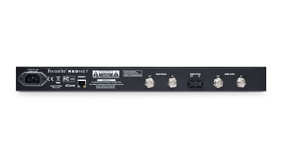
The MADI protocol allows up to 64 channels of digital audio to be sent along a single optical or electrical cable. Focusrite’s RedNet 6 provides connectivity for either option.
Audio Over IP
A single MADI cable can thus carry more channels of audio than most of us are ever likely to need. However, just like ADAT and AES3, it’s a point-to-point connection that can only convey audio from a single source to a single destination. In typical situations where there are a lot of audio channels in play, that restriction becomes too limiting. Consider, for instance, a large studio complex where there are multiple live rooms and control rooms, along with a public performance space. Ideally, we’d want to be able to record audio in any of the control rooms from any of the live rooms and the stage, regardless of what anyone else is also recording, or whether the front-of-house engineer is also mixing for the audience. To enable all of the myriad configurations using any point-to-point standard would be almost impossible; complex cabling and digital patchbays would need to be set up, and adding any new devices into the system would prove a real headache.
A much more versatile solution is to set up not a series of simple one-way data links, but a network: a global pathway that connects all the devices in the studio and allows each of them to pass data to any of the others as needed. The value of this approach has been recognised for many years, and there have been many attempts to create audio networking systems suitable for studios, broadcast and live-sound use. Some of these required their own types of cable and connector, while others made non-standard use of the RJ45 connectors and Cat5 cable that are used for local area networks in computing. Some of these earlier systems are still in widespread use, especially in installation audio and broadcast, but if any sort of standardisation happens in the future, it seems most likely that it will focus on one of the newer standards that can carry audio over a standard network. These include Dante, developed by Audinate and featured in Focusrite’s RedNet and Red products, and Audio Video Bridging, which is an open standard defined by the Institute of Electrical and Electronics Engineers. (If no clear winner emerges from all these competing Ethernet audio standards, it’s not necessarily a disaster, as a standard called AES67 has been developed to allow ‘layer 3’ protocols to talk to one another. Dante is already compliant with AES67, but AVB is a ‘layer 2’ technology and cannot be AES67-compliant without a hardware ‘bridge’.)
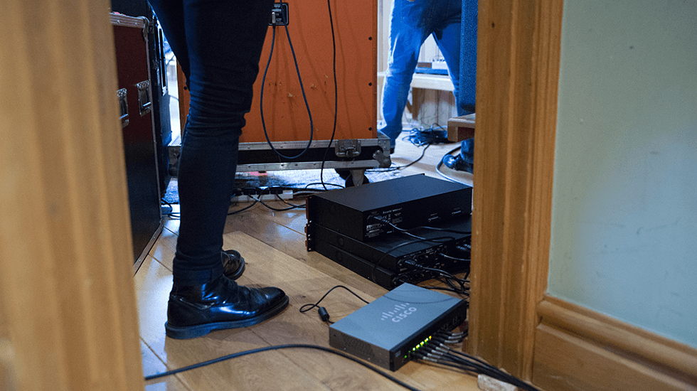
Technologies such as Dante and AVB send audio as standard network traffic, meaning they can make full use of cheap and plentiful network hardware and share it with other data.
Networked audio systems generally need to be configured in software, which means they are not quite as simple as plugging an ADAT preamp into an audio interface. But their great advantage is scalability. More and more devices can be added to the network simply by plugging in a single cable. There is no need for digital patchbays or master clocks, and we have almost complete freedom as to where each device is positioned within the studio complex. What’s more, unlike any of the other standards for making digital audio connections, Ethernet cables can carry power as well as data, allowing devices such as headphone amps and monitor controllers to be freely moved around regardless of the availability of mains power.
Further Reading: Can An External Clock Improve Sound Quality?
External master clocks are often necessary in systems where multiple digital devices need to work together. However, it’s often claimed that there is another reason for using them: namely, that running a digital device from a high-quality master clock rather than its own clock can make it sound better.
It’s true that changing the clock source can make a difference to the subjective sound of a piece of digital equipment. In technical terms, however, doing so can only improve the performance of that equipment if its internal clock is faulty or sub-standard. This is more or less unheard-of in modern audio equipment. So, if you prefer the way your audio interface or analogue-to-digital converter sounds when clocked externally, you may be hearing a real difference, but this is almost certainly down to higher levels of noise and distortion.
This article from Sound On Sound provides a wealth of advice on the topic.
Further Reading: MIDI
As well as sockets that pass analogue and digital audio, some interfaces also feature 5-pin DIN sockets for MIDI In and Out. These don’t convey audio information at all, but a form of control data called Musical Instrument Digital Interface or MIDI. The MIDI standard was developed in the early 1980s to provide a way for keyboards, synths, sequencers and samplers from different manufacturers to interact. The MIDI data format is still in widespread use today, and although new instruments more often send it to host computers over a USB cable, it can be useful to have some hardware MIDI ports to control older equipment.
Further Reading: Aggregate To Accumulate?
In theory, the simplest way to expand a computer-based recording system would be to add more than one audio interface to it. In practice, however, this often isn’t an option, especially if you want to combine interfaces from different manufacturers. The ASIO driver protocol used by most Windows recording software can only interact with a single device: you can’t even use different interfaces for input and output, let alone combine the inputs from two or more separate interfaces. Apple’s Core Audio standard is more flexible in this department, and allows the inputs and outputs on multiple interfaces to be combined into a single ‘aggregate’ device. However, the aggregate devices are often unreliable and slow, and even if they work correctly, will leave you having to interact with two or more sets of driver and control panel software, as well as your recording software, so this approach is definitely not recommended.
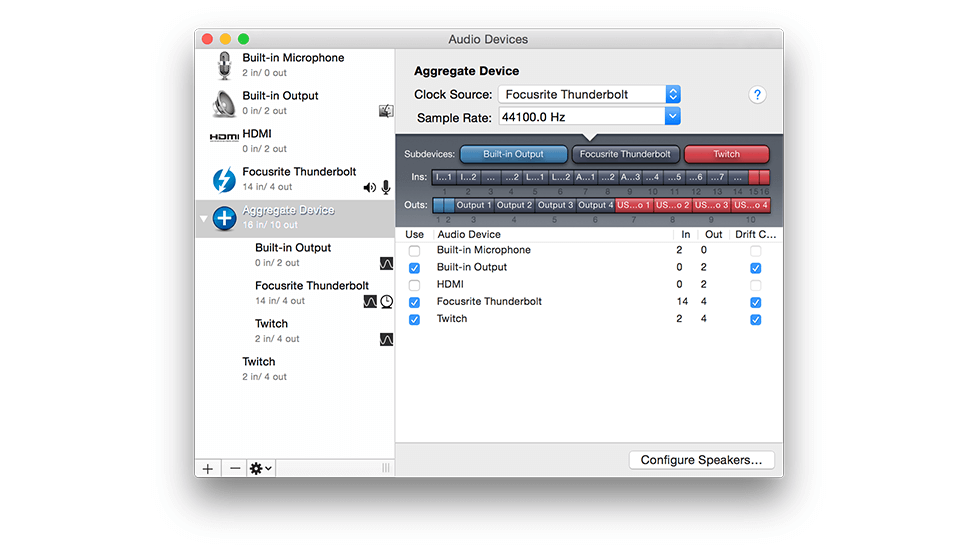
Aggregate Devices in Apple OSX’s Core Audio allow multiple audio interfaces to be combined, but performance is often poor.
More practical is the option of combining multiple interfaces of the same type. In this arrangement, the driver software is designed to present all the connected interfaces to the recording software and operating system as a single unit. It’s only feasible where the manufacturer’s driver and control panel software has been specially written to enable it. This is easier to achieve with PCIe and Thunderbolt audio interfaces than it is with USB, so there are very few USB interfaces that support this sort of ‘daisy-chaining’.
This sort of expansion is most useful with modular systems such as Pro Tools HDX, where adding additional PCIe cards increases the total number of inputs and outputs, but still leaves you free to choose what form those inputs and outputs should take. Ethernet audio protocols such as Dante and AVB take this flexibility much further, allowing any combination of the devices attached to the network to be viewed as a single multi-channel interface by your recording software.
Words: Sam Pryor